Discover great apps, games, extensions and themes for Google Chrome. Small programmes that add new features to your browser and personalise your browsing experience. Manage your extensions. On your computer, open Chrome. At the top right, click More More tools Extensions.; Make your changes: Turn on/off: Turn the extension on or off. Allow incognito: On the extension, click Details.Turn on Allow in incognito.; Fix corruptions: Find a corrupted extension and click Repair.Confirm by clicking Repair extension.; Allow site access: On the extension, click Details. Small programs that add new features to your browser and personalize your browsing experience. Navigate to chrome://extensions in your browser. You can also access this page by clicking on the Chrome menu on the top right side of the Omnibox, hovering over More Tools and selecting Extensions. Check the box next to Developer Mode. Click Load Unpacked Extension and select the directory for your 'Hello Extensions' extension.

- Vhdl Code
- Vhdl Code For 1 To 4 Demultiplexer Using Structural Modelling
- Vhdl Multiplexer Code
- Vhdl Code For 1 To 4 Demultiplexer Using Dataflow Modelling
Design of 4 to 1 Multiplexer using if-else statement (VHDL Code). Design of 4 to 1 Multiplexer using if - else statement (Behavior Modeling Style)- Output Waveform: 4 to 1 Multiplexer VHDL. To design a 4:1 MULTIPLEXER in VHDL in Dataflow style of modelling and verify. Code: library ieee; use ieee.stdlogic1164.all; entity mux4 is port.
Vhdl Code
Vhdl Code For 1 To 4 Demultiplexer Using Structural Modelling
-- inputs: 1-bit sel (selector), 4-bit X, 4-bit Y
-- outputs: 4-bit m
LIBRARY ieee;
USE ieee.std_logic_1164.all;
entity MUX8_4 is
PORT( sel: in bit;
X, Y: in bit_vector(3 downto 0);
m: out bit_vector(3 downto 0));
end MUX8_4;
architecture logic of MUX8_4 is
component MUX4_2 is
PORT( sel, X0, X1, Y0, Y1: in bit;
m0, m1: out bit);
end component;
begin
mux4_2_inst0 : MUX4_2
PORT MAP( sel => sel, X0 => X(0), X1 => X(1), Y0 => Y(0), Y1 => Y(1),
m0 => m(0), m1 => m(1));
mux4_2_inst1 : MUX4_2
PORT MAP( sel => sel, X0 => X(2), X1 => X(3), Y0 => Y(2), Y1 => Y(3),
m0 => m(2), m1 => m(3));
end logic;
Verilog Code for 1 to 4 DEMUX | 1 to 4 DEMUX Verilog Code
Vhdl Multiplexer Code
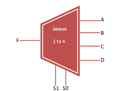
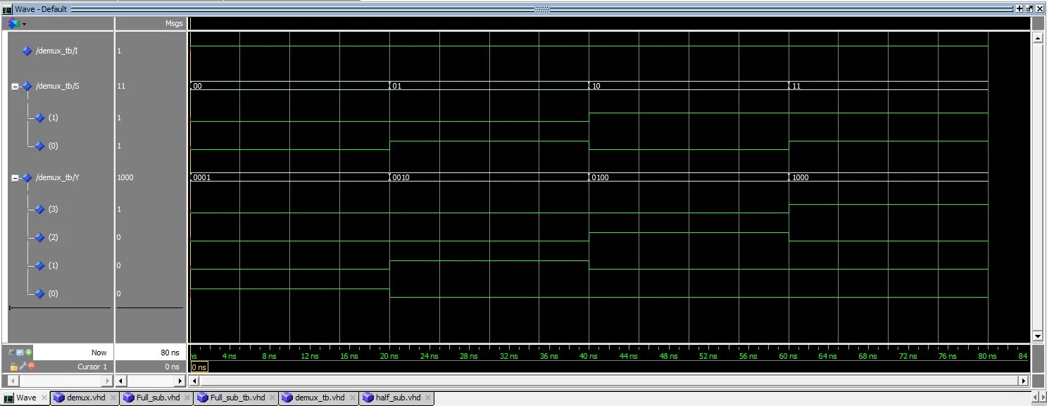
This page of Verilog source code section covers 1 to 4 DEMUX Verilog code.The block diagram and truth table of 1 to 4 DEMUX Verilog code is also mentioned.
Block Diagram of 1 to 4 DEMUX
Truth Table of 1 to 4 DEMUX
1 to 4 DEMUX Verilog code
input a_in;
input [1:0] sel;
output [3:0] y_out;
reg [3:0] y_out;
always @(a_in, sel)
begin
case (sel)
2'b00:begin y_out[0]=a_in; y_out[1]= 1'b0;
y_out[2]= 1'b0;y_out[3]=1'b0; end
2'b01: begin y_out[0]= 1'b0;y_out[1]=a_in;
y_out[2]= 1'b0;y_out[3]=1'b0; end
2'b10: begin y_out[0]= 1'b0;y_out[1]=1'b0;
y_out[2]=a_in; y_out[3]=1'b0; end
2'b11: begin y_out[0]= 1'b0; y_out[1]= 1'b0;
y_out[2]=1'b0;y_out[3]=a_in; end
default: y_out=3'b000;
endcase
end
endmodule
USEFUL LINKS to VHDL CODES
Refer following as well as links mentioned on left side panel for useful VHDL codes.
D Flipflop
T Flipflop
Read Write RAM
4X1 MUX
4 bit binary counter
Radix4 Butterfly
16QAM Modulation
2bit Parallel to serial

Vhdl Code For 1 To 4 Demultiplexer Using Dataflow Modelling
USEFUL LINKS to Verilog Codes
Following are the links to useful Verilog codes.
Low Pass FIR Filter
Asynchronous FIFO design with verilog code
D FF without reset
D FF synchronous reset
1 bit 4 bit comparator
All Logic Gates
RF and Wireless tutorials


- Vhdl Code
- Vhdl Code For 1 To 4 Demultiplexer Using Structural Modelling
- Vhdl Multiplexer Code
- Vhdl Code For 1 To 4 Demultiplexer Using Dataflow Modelling
Design of 4 to 1 Multiplexer using if-else statement (VHDL Code). Design of 4 to 1 Multiplexer using if - else statement (Behavior Modeling Style)- Output Waveform: 4 to 1 Multiplexer VHDL. To design a 4:1 MULTIPLEXER in VHDL in Dataflow style of modelling and verify. Code: library ieee; use ieee.stdlogic1164.all; entity mux4 is port.
Vhdl Code
Vhdl Code For 1 To 4 Demultiplexer Using Structural Modelling
-- inputs: 1-bit sel (selector), 4-bit X, 4-bit Y
-- outputs: 4-bit m
LIBRARY ieee;
USE ieee.std_logic_1164.all;
entity MUX8_4 is
PORT( sel: in bit;
X, Y: in bit_vector(3 downto 0);
m: out bit_vector(3 downto 0));
end MUX8_4;
architecture logic of MUX8_4 is
component MUX4_2 is
PORT( sel, X0, X1, Y0, Y1: in bit;
m0, m1: out bit);
end component;
begin
mux4_2_inst0 : MUX4_2
PORT MAP( sel => sel, X0 => X(0), X1 => X(1), Y0 => Y(0), Y1 => Y(1),
m0 => m(0), m1 => m(1));
mux4_2_inst1 : MUX4_2
PORT MAP( sel => sel, X0 => X(2), X1 => X(3), Y0 => Y(2), Y1 => Y(3),
m0 => m(2), m1 => m(3));
end logic;
Verilog Code for 1 to 4 DEMUX | 1 to 4 DEMUX Verilog Code
Vhdl Multiplexer Code
This page of Verilog source code section covers 1 to 4 DEMUX Verilog code.The block diagram and truth table of 1 to 4 DEMUX Verilog code is also mentioned.
Block Diagram of 1 to 4 DEMUX
Truth Table of 1 to 4 DEMUX
1 to 4 DEMUX Verilog code
input a_in;
input [1:0] sel;
output [3:0] y_out;
reg [3:0] y_out;
always @(a_in, sel)
begin
case (sel)
2'b00:begin y_out[0]=a_in; y_out[1]= 1'b0;
y_out[2]= 1'b0;y_out[3]=1'b0; end
2'b01: begin y_out[0]= 1'b0;y_out[1]=a_in;
y_out[2]= 1'b0;y_out[3]=1'b0; end
2'b10: begin y_out[0]= 1'b0;y_out[1]=1'b0;
y_out[2]=a_in; y_out[3]=1'b0; end
2'b11: begin y_out[0]= 1'b0; y_out[1]= 1'b0;
y_out[2]=1'b0;y_out[3]=a_in; end
default: y_out=3'b000;
endcase
end
endmodule
USEFUL LINKS to VHDL CODES
Refer following as well as links mentioned on left side panel for useful VHDL codes.
D Flipflop
T Flipflop
Read Write RAM
4X1 MUX
4 bit binary counter
Radix4 Butterfly
16QAM Modulation
2bit Parallel to serial
Vhdl Code For 1 To 4 Demultiplexer Using Dataflow Modelling
USEFUL LINKS to Verilog Codes
Following are the links to useful Verilog codes.
Low Pass FIR Filter
Asynchronous FIFO design with verilog code
D FF without reset
D FF synchronous reset
1 bit 4 bit comparator
All Logic Gates
RF and Wireless tutorials
Share this page
Translate this page
